

Load Bearing Wall Removal Calculations: 5 Expert Steps for 2026
Removing a load bearing wall requires precise structural calculations to ensure your home’s safety and meet building codes. We’ve written this guide for homeowners, contractors, and DIY enthusiasts who need to understand the engineering behind safe wall removal projects.
Our comprehensive breakdown covers the essential calculations you’ll need before starting your project. We’ll walk you through understanding load calculations for bearing wall removal, including how to determine the total weight your new support system must handle. You’ll also learn about beam size requirements and specifications, so you can select the right steel or engineered lumber beam for your specific situation.
sizing replacement beams
We’ll also dive into structural support and connection details, showing you how to properly secure your new beam to existing framing and foundation elements. Finally, we’ll cover foundation and footing considerations, helping you determine if your existing foundation can handle the concentrated loads or if modifications are needed.
Understanding Load Calculations for Bearing Wall Removal
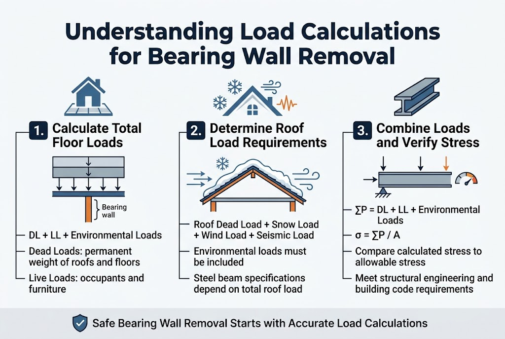
Calculate Total Floor Loads on the Bearing Wall
When calculating total floor loads on bearing walls, we determine the sum of dead loads and live loads that the wall must support. Dead loads include the permanent weight of roofs and floors, while live loads encompass variable loads such as occupants and furniture. For accurate load bearing wall removal calculations, we use the equation: ΣP = DL + LL + Environmental Loads, where the total load represents the cumulative weight transferred to the foundation through the structural wall system.
Determine Roof Load Requirements and Snow Load Factors
We calculate roof load requirements by considering both the permanent dead load from roofing materials and variable live loads including snow loads where applicable. Environmental loads such as wind and seismic forces must be factored into our structural calculations to ensure comprehensive load analysis. These calculations form the foundation for determining appropriate steel beam specifications when removing load-bearing walls.
Combine Dead Loads and Live Loads for Accurate Calculations
We combine all load components to establish the total design load that replacement structural elements must support. Our calculations verify that stress levels remain within allowable limits by comparing the calculated stress (σ = ΣP / A) against material allowable stress values. This comprehensive approach ensures that load bearing wall removal calculations meet structural engineering requirements and building code compliance for safe construction practices.
Beam Size Requirements and Specifications
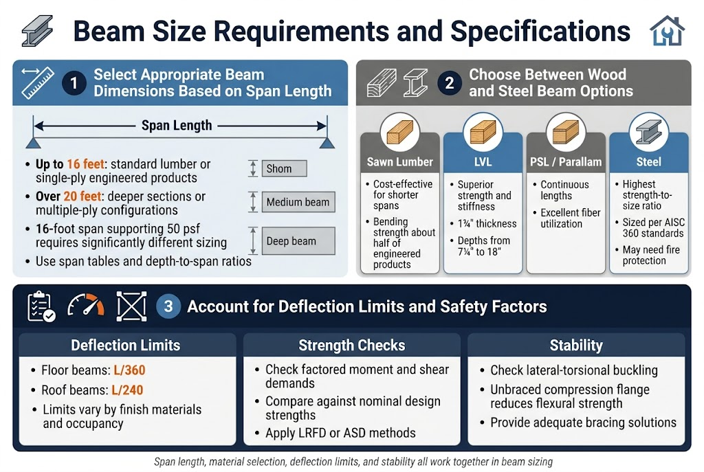
Select Appropriate Beam Dimensions Based on Span Length
When determining beam dimensions for load bearing wall removal, we must consider the span length as our primary factor. For spans up to 16 feet, we can often utilize standard lumber dimensions or single-ply engineered products. However, as spans increase beyond 20 feet, we need to evaluate deeper sections or multiple-ply configurations. Our calculations show that a 16-foot span supporting 50 psf requires significantly different sizing than shorter applications. We use span tables to match our required span with appropriate depth-to-span ratios, ensuring both strength and deflection criteria are met.
Choose Between Wood and Steel Beam Options
We have several material options when sizing replacement beams, each with distinct performance characteristics. Sawn lumber offers cost-effectiveness for shorter spans but has bending strength limitations, typically only half that of engineered products. LVL provides superior strength and stiffness, coming in 1¾” thickness with depths from 7¼” to 18″. For longer spans, we consider Parallam (PSL) which offers continuous lengths with excellent fiber utilization, or steel beams sized per AISC 360 standards. Steel beams provide the highest strength-to-size ratio but require different connection details and may need fire protection depending on building codes.
Account for Deflection Limits and Safety Factors
Our beam calculations must satisfy both strength requirements and deflection limits to ensure proper performance. We typically apply L/360 deflection limits for floor applications and L/240 for roof beams, though these can vary based on finish materials and occupancy. The design process involves checking factored moment and shear demands against nominal design strengths, with appropriate safety factors applied through LRFD or ASD methods. We must also consider lateral-torsional buckling effects, where unbraced length of the compression flange can significantly reduce available flexural strength, requiring adequate bracing solutions in our structural support design.
Structural Support and Connection Details
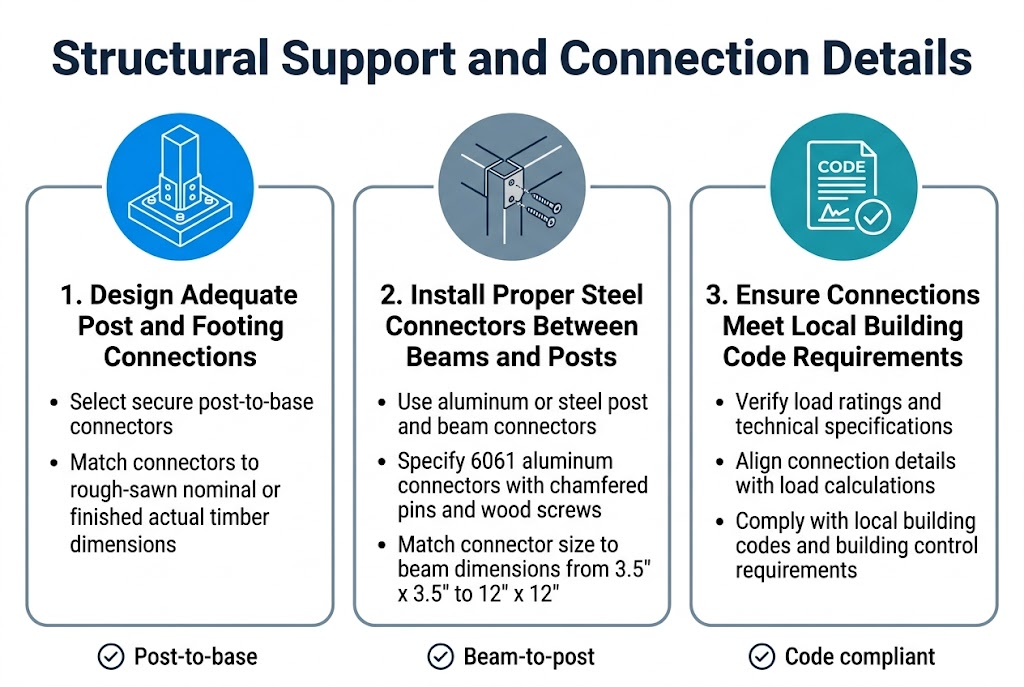
Design Adequate Post and Footing Connections
Now that we have covered the beam requirements, we need to establish secure post-to-base connections using specialized connectors that meet structural demands. We must select connectors sized appropriately for our timber dimensions, whether rough-sawn nominal or finished actual measurements.
load bearing wall removal
Install Proper Steel Connectors Between Beams and Posts
With foundation considerations in mind, we’ll implement aluminum or steel connectors designed for post and beam construction. We recommend using 6061 aluminum connectors with chamfered pins and appropriate wood screws, ensuring the connector size matches our beam dimensions from 3.5″ x 3.5″ to 12″ x 12″ for optimal structural integrity.
Ensure Connections Meet Local Building Code Requirements
Previously established load calculations must align with our connection specifications to satisfy local building codes. We need to verify that our selected connectors provide adequate load ratings and technical specifications that comply with structural requirements for load bearing wall removal calculations and steel beam structural calculations mandated by building control authorities.
Maintain Structural Stability After load bearing wall removal
When we remove load-bearing walls, maintaining lateral stability becomes crucial as we lose critical structural support that previously provided lateral resistance. We must address the potential for structural instability by implementing proper bracing solutions that compensate for the removed wall sections. Our approach should include installing metal framing straps from beam ends to remaining wall sections, which provides essential lateral support and maintains overall structural integrity. Additionally, we recommend preserving the existing double top plates whenever possible, as these elements act as chord ties that contribute significantly to the building’s lateral stability system.
Install Plywood Sheathing or Alternative Bracing Methods
We can implement several effective bracing methods to restore lateral stability after wall removal. Metal framing straps represent one of our primary solutions, particularly when connecting new beams to existing wall sections. These connections help transfer lateral forces and maintain structural continuity throughout the modified structure. We should also consider the existing roof framing system’s contribution to lateral stability, ensuring that our bracing solutions work in harmony with the overall structural design.
Address Loss of Lateral Support From Removed Wall Sections
The removal of wall sections creates deficiencies in our lateral bracing system, particularly in high seismic or wind regions where lateral forces are more significant. We must carefully evaluate how the removed walls previously contributed to the building’s resistance against lateral loads and implement compensatory measures accordingly. Our structural modifications should account for the complete load path from roof to foundation, ensuring that lateral forces can still be effectively transferred through the remaining structural elements and any new bracing systems we install.
load bearing wall removal calculations careful consideration of multiple structural elements working together as a system. We’ve explored the critical calculations for determining beam sizes, the importance of proper connections to existing footings, and the need for lateral bracing solutions to maintain structural integrity. Each component – from understanding load distributions of 882 pounds per linear foot in typical residential applications to specifying adequate beam sizes like the equivalent of a 4×10 for an 8-foot opening – plays a vital role in ensuring safe wall removal.
The complexity of these calculations, involving foundation adequacy, connection details, and lateral stability measures, underscores why professional structural engineering is essential for load bearing wall modifications. We strongly recommend consulting with a qualified structural engineer who can perform site-specific calculations, verify existing foundation capacity, and provide detailed connection specifications. This investment in professional expertise ensures your project meets building codes, maintains structural safety, and protects your property’s long-term integrity.
load bearing wall removal calculations